After restoring the microscope, purchasing a light and slides a case was needed. The microscope is approximately 5" X 7" X 12". After looking at a few cases online a plan was sketched out. The inner dimensions of the case are 6" X 11" X 13". 1/2" lumber was purchased. These boards are approximately 3 1/2" wide. Two boards will be glued to make the deep sides. Three drawers are planned as well. One will hold the light. One is for the slides, coverslips, and stains. The last is for any additional lenses or filters purchased.
The top and bottom will be 6 3/4" X 12". Four boards were cut to 12 1/2". Similarly, the sides will be 6" X 13". Four 13 1/2" boards were cut for the sides. The door will be 12" X 13". It will be made in a frame and panel style. The outer frame members were cut: two at 13 1/2" and two at 12 1/2".
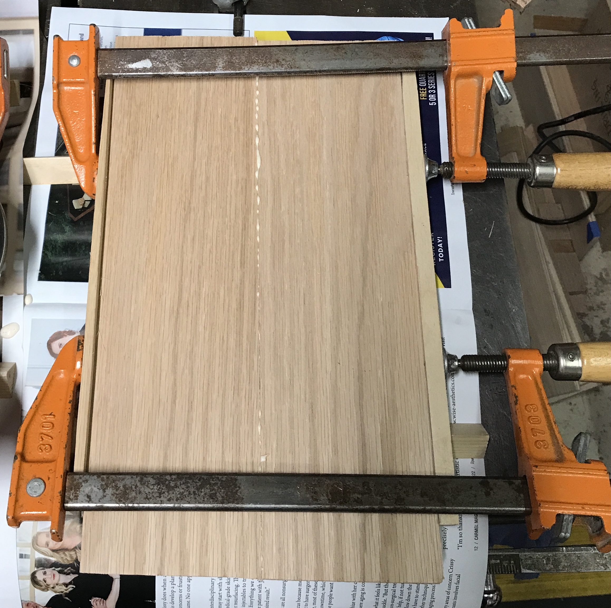
Mating edges were decided for the top, bottom and sides. These edges were planed. During the plane rehab course a trick was discussed of planing the center portion of an edge (leaving an inch at either end unplaned). In this fashion only one clamp is needed in the center of a pair of boards. An attempt was made to plane the center of one board of a pair, but I had little success attempting this. The planed edges did, however, fit well. The first two pairs of boards were glued up at 8 am. Only two can be glued at a time, as there are only four clamps available. The photo shows the glue-up.
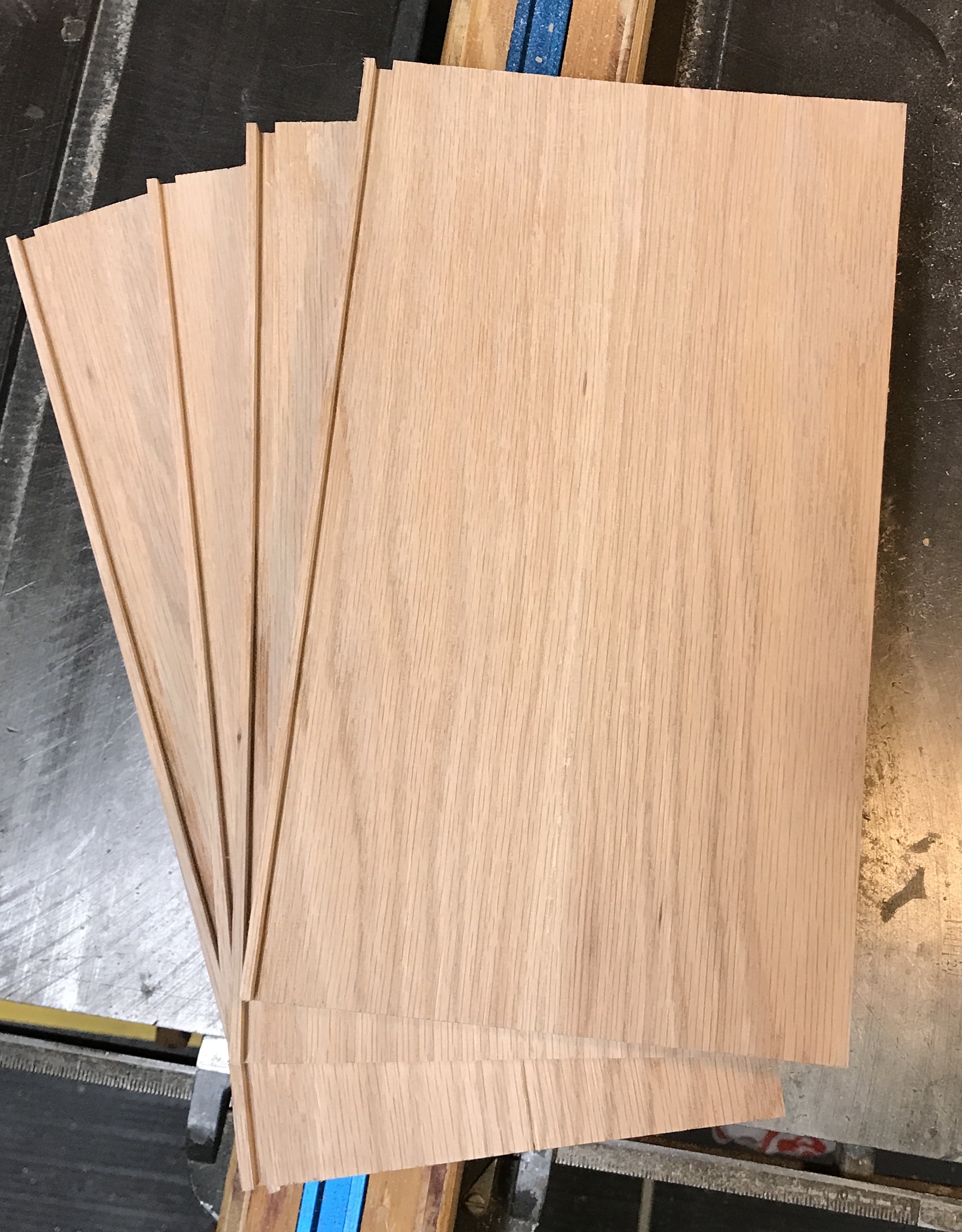
The second pairs were glued up an hour later. After a few hours the clamps were removed. All four glue-ups were allowed to dry for two days. The majority of the glue squeeze-out was removed with a chisel. Only one of the four boards was even across the joint. After trying many things the easiest way to fix this was by sanding with 40 grit paper using the oscillating sander. This left the four boards ready for cutting to size.
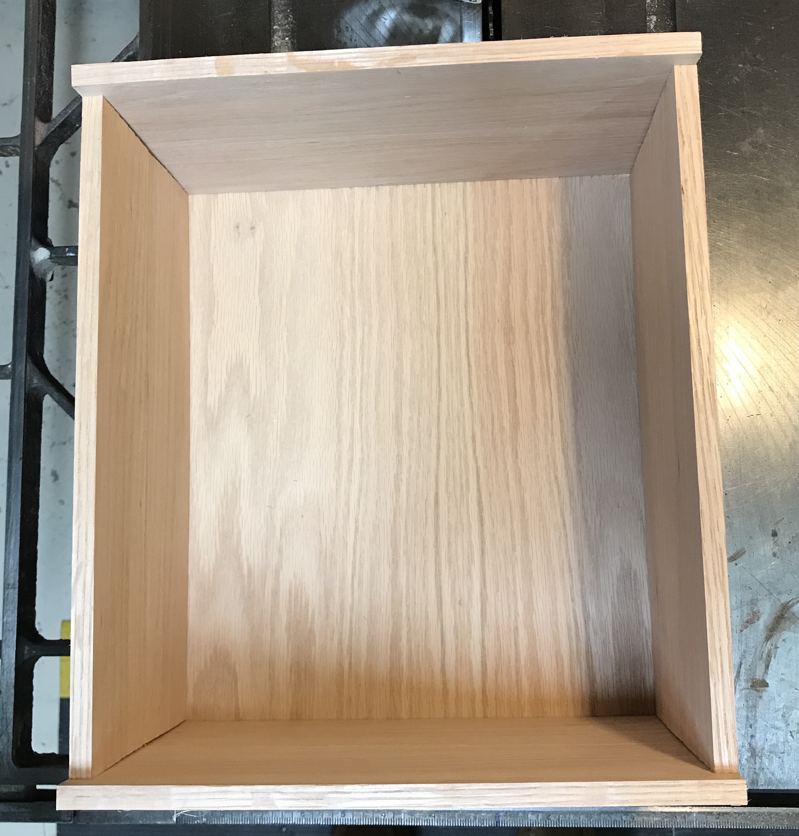
The planned inside depth is 6 3/4". The current width of the boards is 7 1/16". The back needs to sit in a 1/4" dado. The dado will be 1/8" from the back edges. This leaves the inside depth at 6 11/16". Close enough. All four sides of the box need one end squared up and then cut to length. The two sides need 1/2" removed from the front side for the inset door.
One edge of each board was squared up with the crosscut sled on the table saw. The boards were cut to length, two at 12" and two at 13" using a stop. The two long boards, sides, had 1/2" sawed off a long edge. The outside faces were marked.
The thickness of the back was measured at 3/16". The minimal thickness of the dado set is 1/4". The adjustable dado was used with the standard blade. The #2 setting was too wide, so the #1 setting was used. The blade was set to 1/4" height and the fence was set at 1/8" from the blade. After two practice cuts the dados were cut on the inside faces. Due to the marked curve across two of the boards the dado is at some ends less than 1/4" deep. The back will need to be cut smaller than the plan might indicate at 11 1/2"" X 13 1/2"".
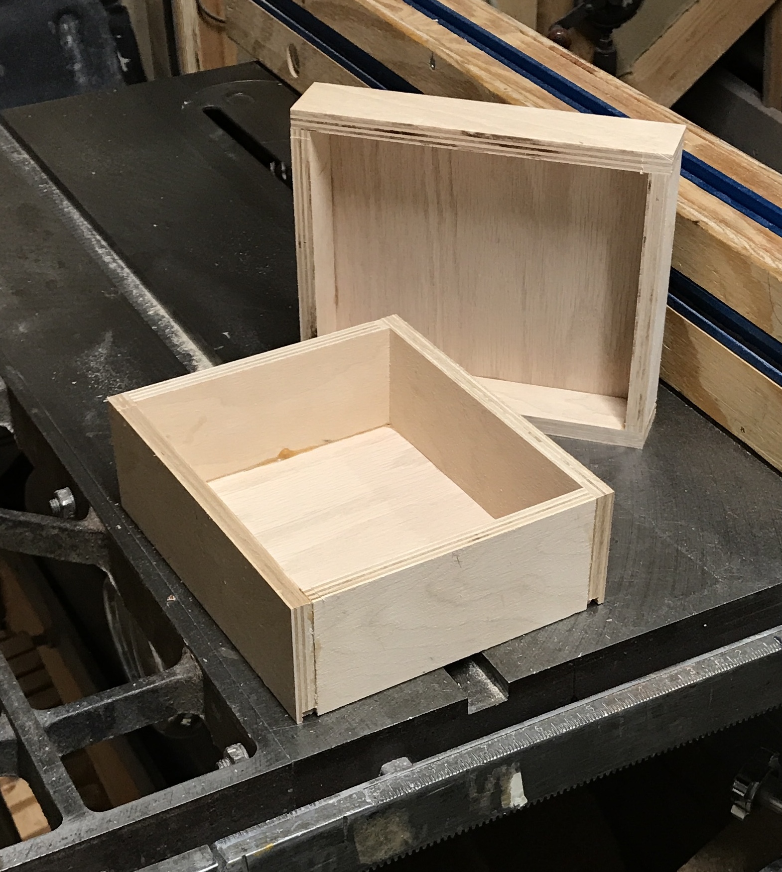
Before the box is assembled the back has to be cut and all parts sanded. The back was cut to 11 3/8" X 13 3/8". It fits within the dadoes leaving the desired internal dimensions. All five parts were sanded with 220 grit paper.
A line was drawn 3/16" from the short ends of both top and bottom box parts. Cross hatches were drawn across the lines at 1 3/8", four per end. The layout lines were punched. Using the #6 wood screw drill guide holes were drilled at each of these locations. Care was taken to drill the chamfers to the same depth. After drilling all sixteen holes the hole was widened to a through hole for a #6 screw. (Only the bottom of the hole needed this treatment.) A side was clamped to the top. The hole in the top was used to guide the drill for a hole in the side. A screw was inserted. The second hole was visible above the clamp, so it was also drilled and a screw inserted. The clamp was removed and the other two holes were drilled and screwed. This was repeated on the other end of the top, but was suspended when the drill ran out of power.
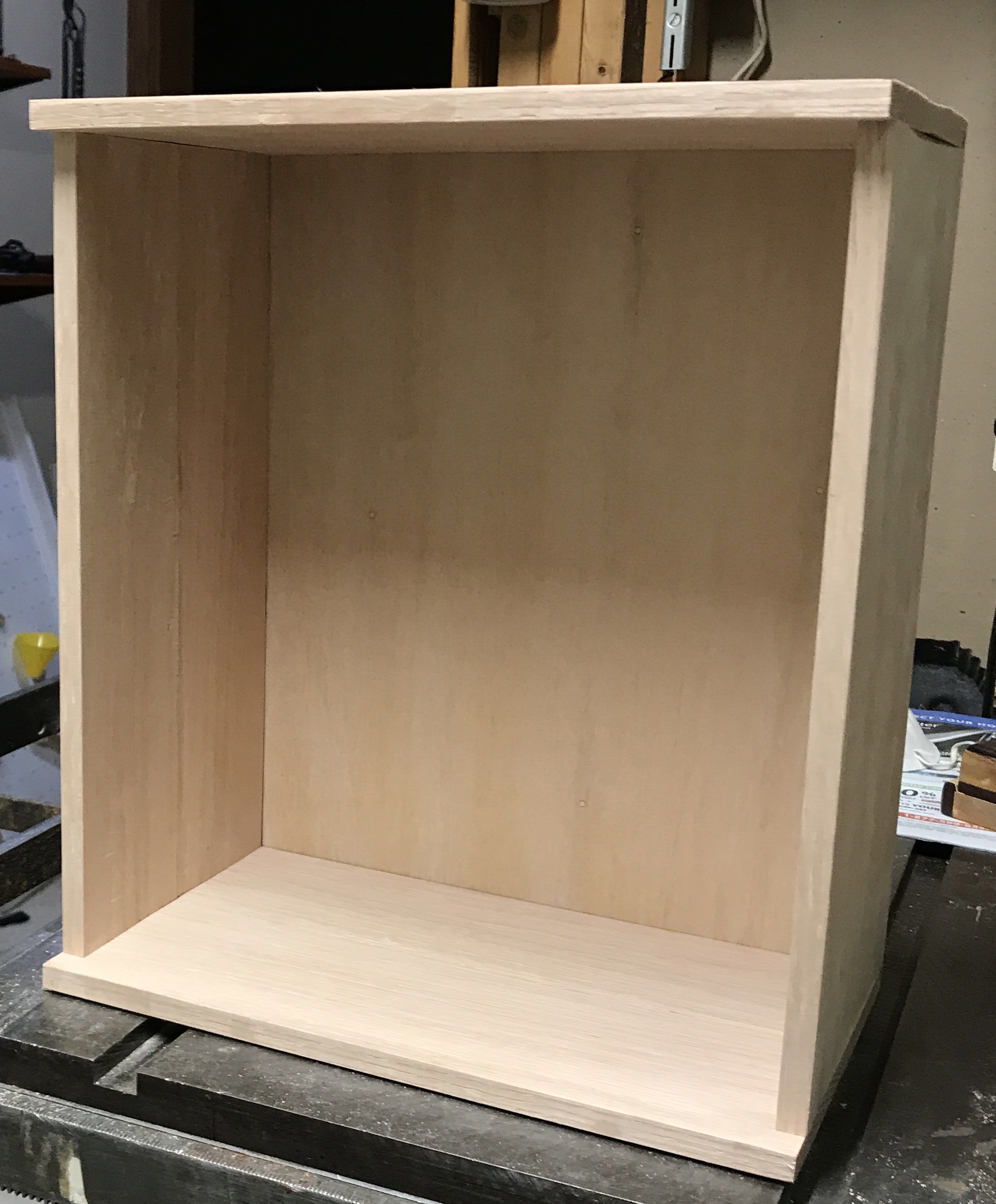
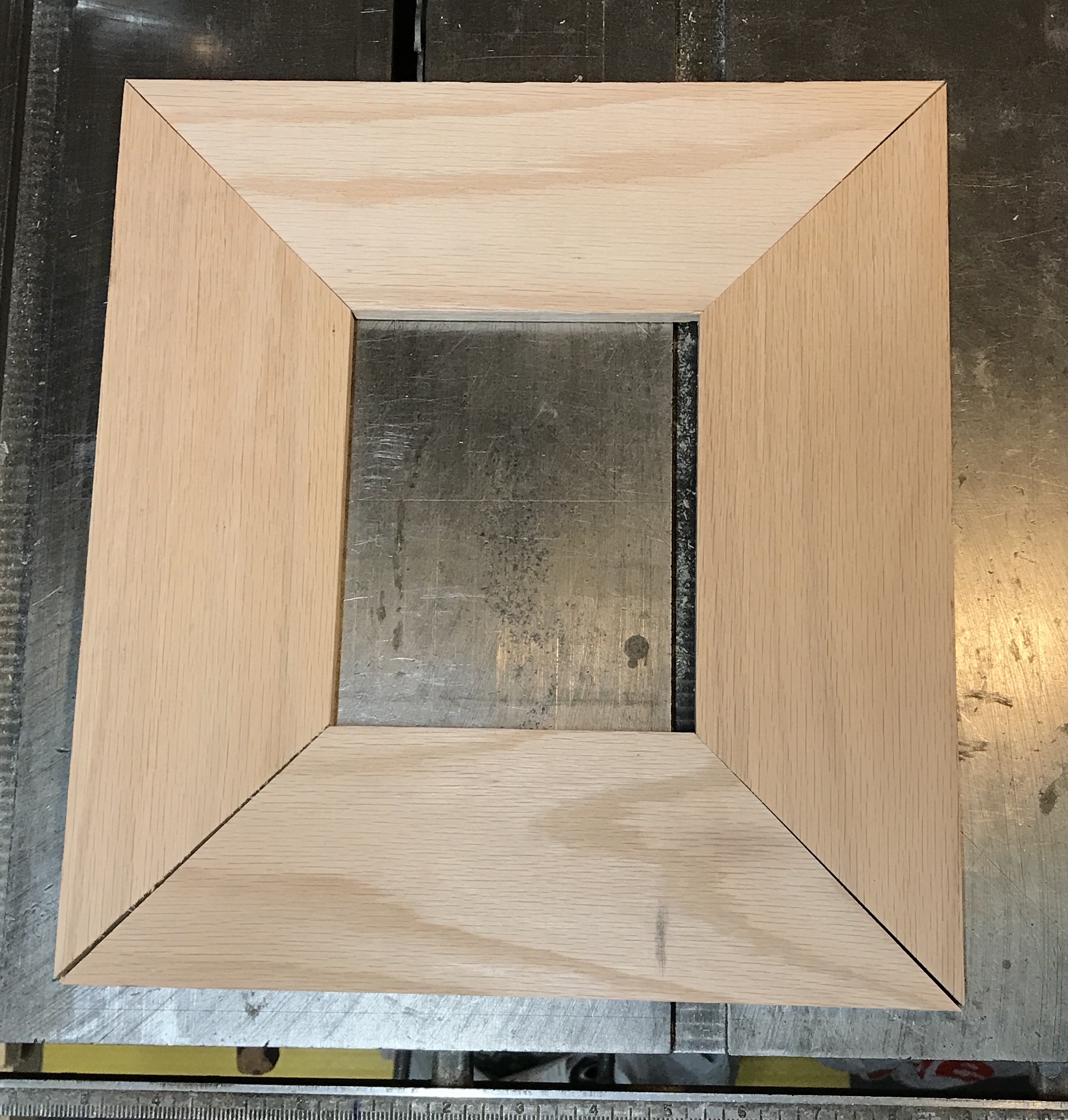
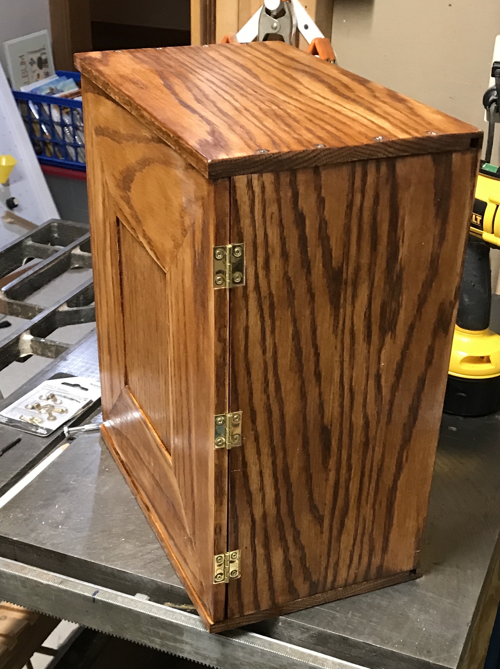
The remainder of the screws were installed on the top and bottom. The completed case body is shown in the two photos below.
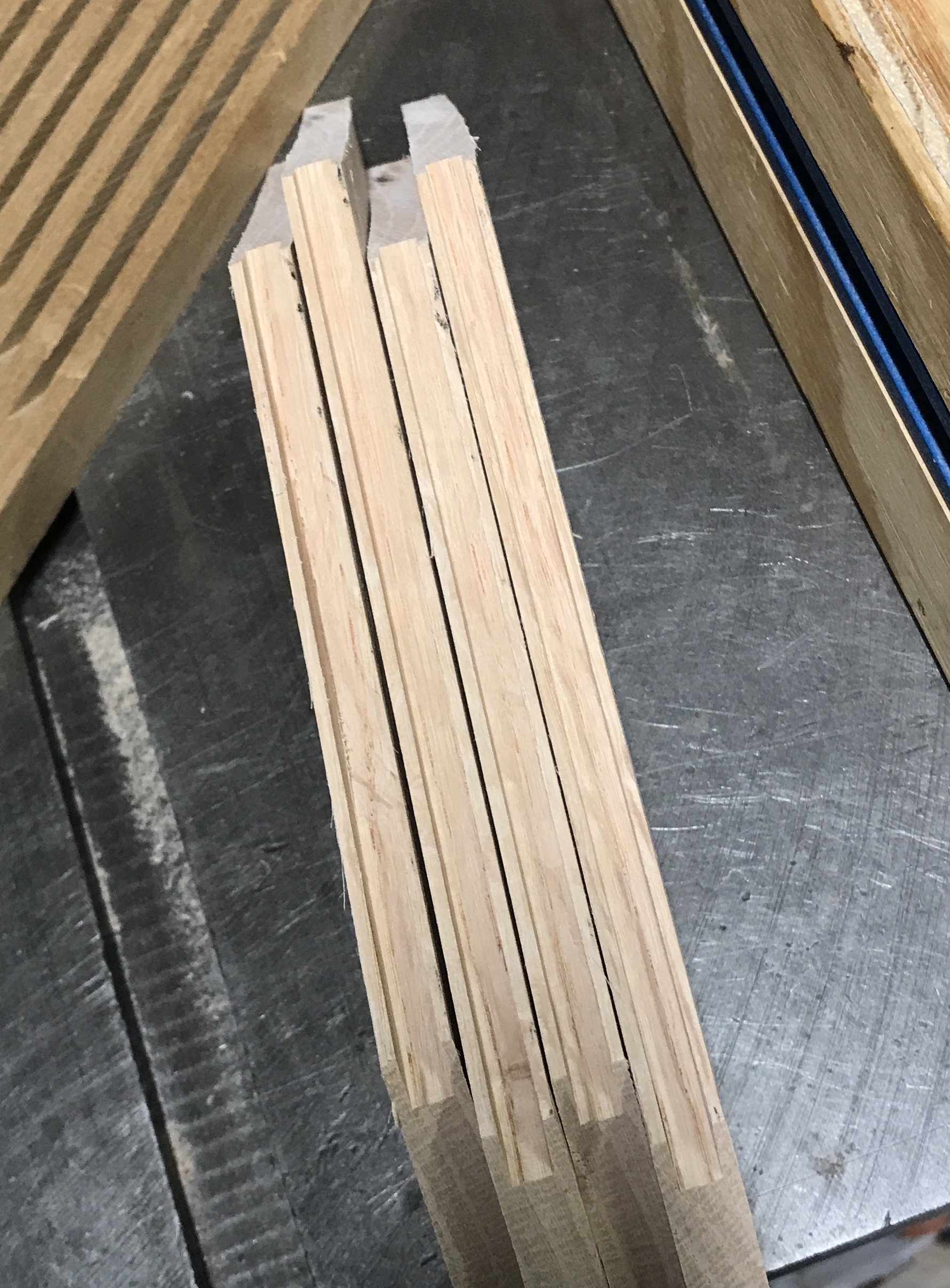
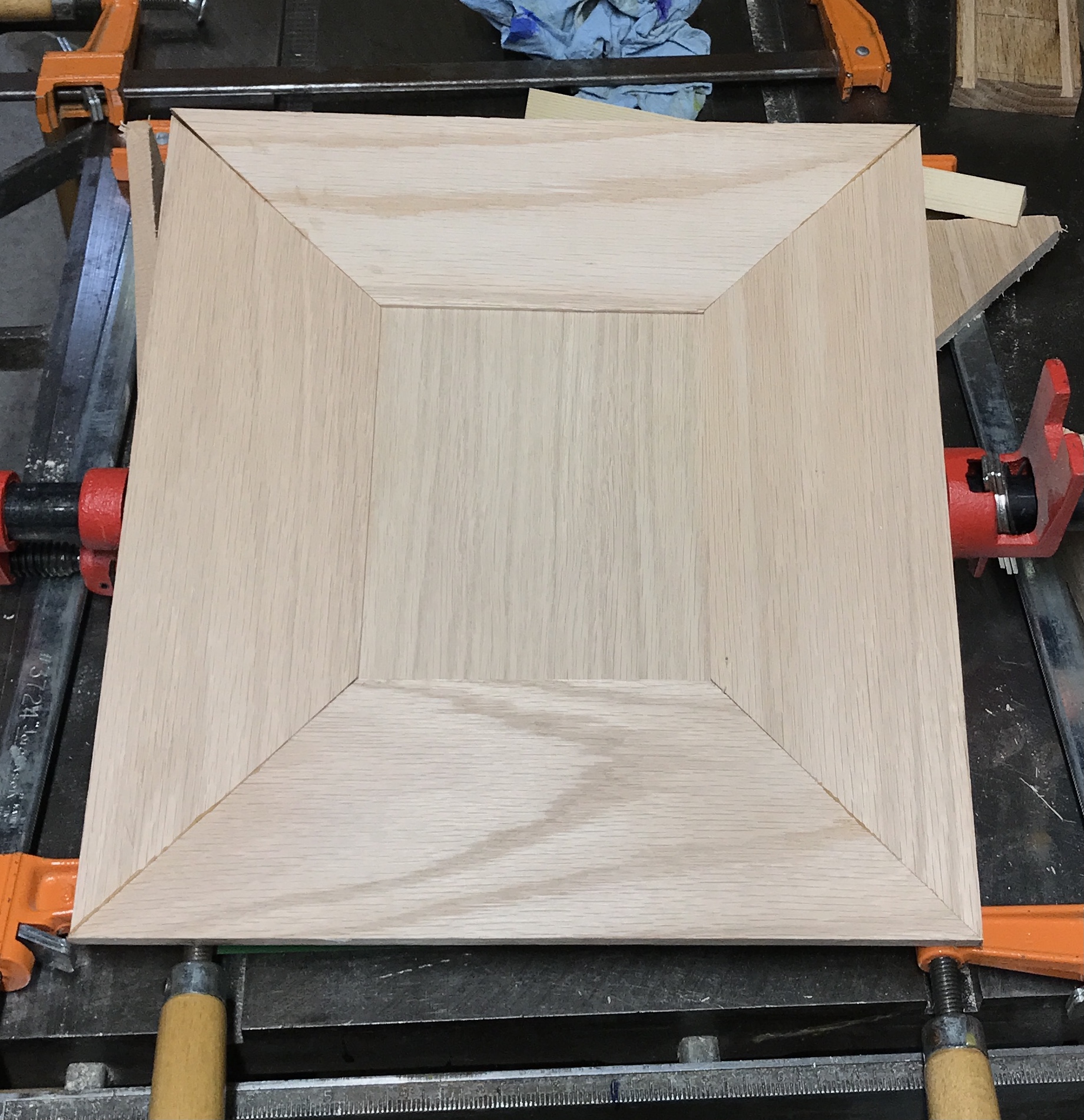
The opening for the door is 12" X 13" and is reasonably square. The height is slightly larger than 13", so a 13" door will leave some space for movement. The door will be a panel and frame construction. The frame will be mitered and the inside edges will sport a dado for the panel. The boards were all mitered at 45° on one end. They were measured and marked for the other end and mitered to length. The fit was a little off, as expected. The inner edges of the joint were filed to achieve a better fit, seen below.
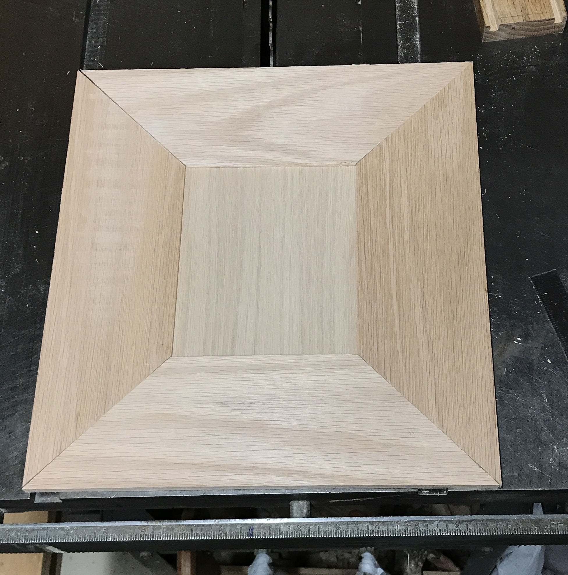
The dado washer set was again used with the fence set 1/16" from the blade. This gave a centered dado to fit the panel, shown in the photo below. The panel was cut to 5 3/8" X 6 3/8". The photo shows how the parts fit.
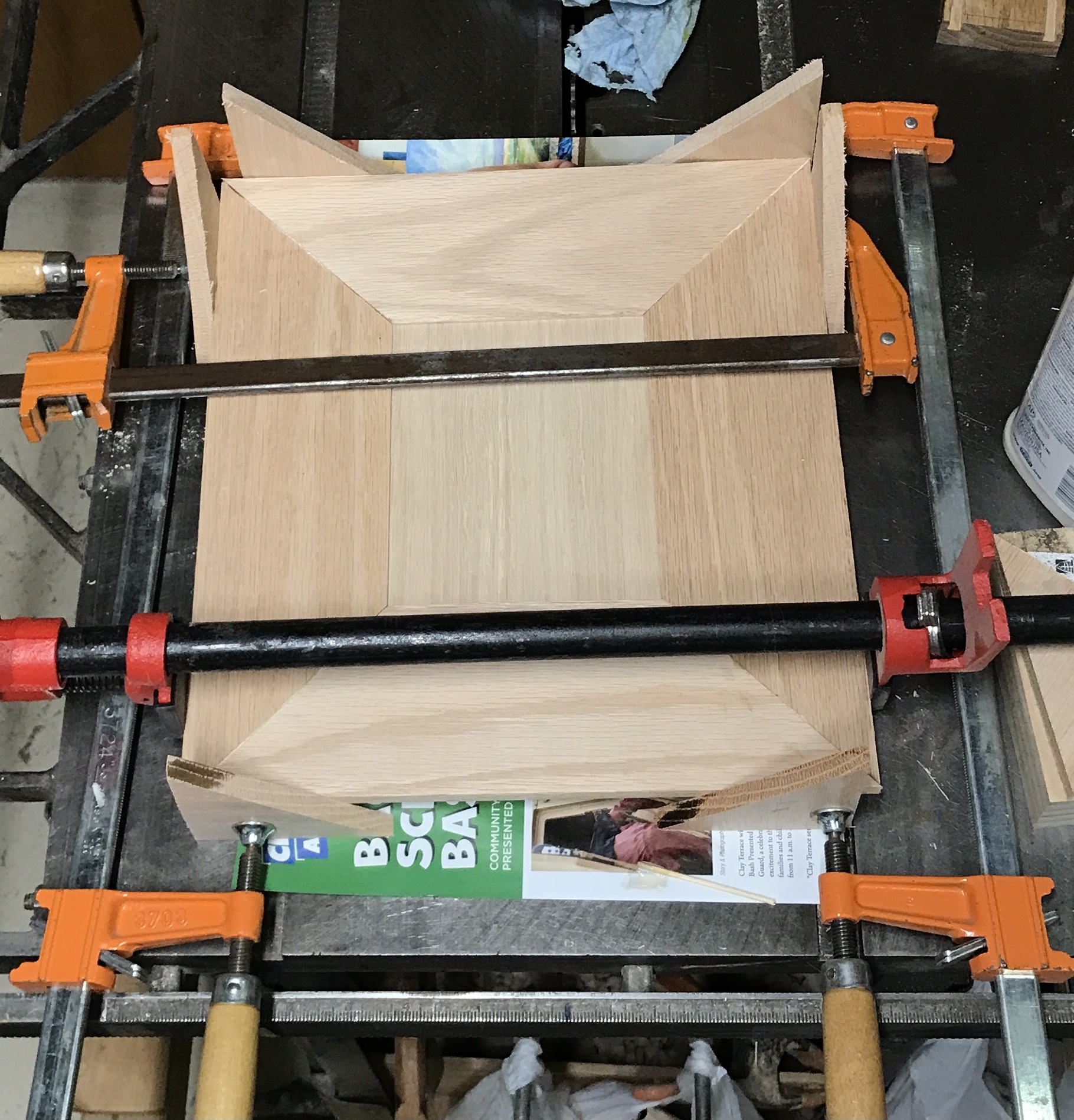
Clamping was challenging. Only three of the bar clamps fit, so a pipe clamp had to be used. The door was assembled on top of triangular bars. Wood was used as needed to protect the door from the clamps. The biggest challenge, beyond getting the clamps properly adjusted, was keeping the door frames flat. This was partially accomplished. A lot of sanding is in store. The photo shows the glue-up. The clamps were removed after two hours. The door does not quite fit as one corner was not pulled together (upper left). It shouldn't take much to make it fit.
A magnetic catch for the door was the initial plan. I have reconsidered. Something more positive is needed in case the case were to fall over. Right now a hook seems like the best choice.
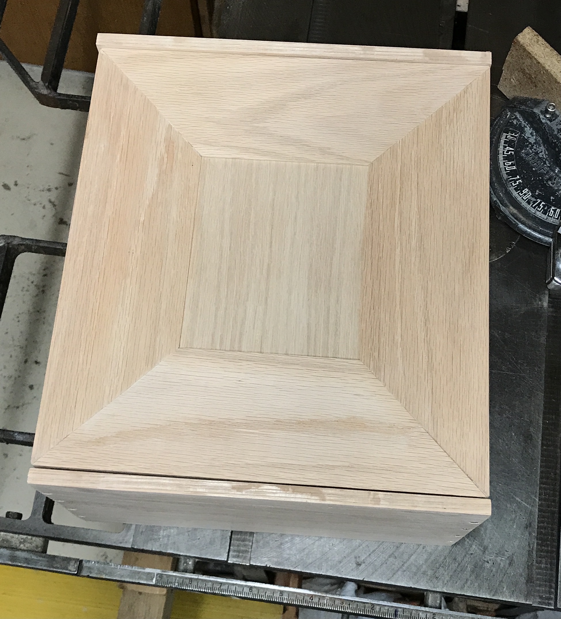
The door was sanded first with 120 grit on the oscillating sander. This did a pretty good job leveling the corners. The front was done as completely as possibility. Glue was used to fill in the cracks during sanding. 220 grit was done by hand. The edges were sanded and all sharp corners were sanded round. The fit showed one corner off by less than a 1/16". The door was clamped to the front of the workbench and the offending corner was planed. This led to an almost perfect as seen in the photo below.
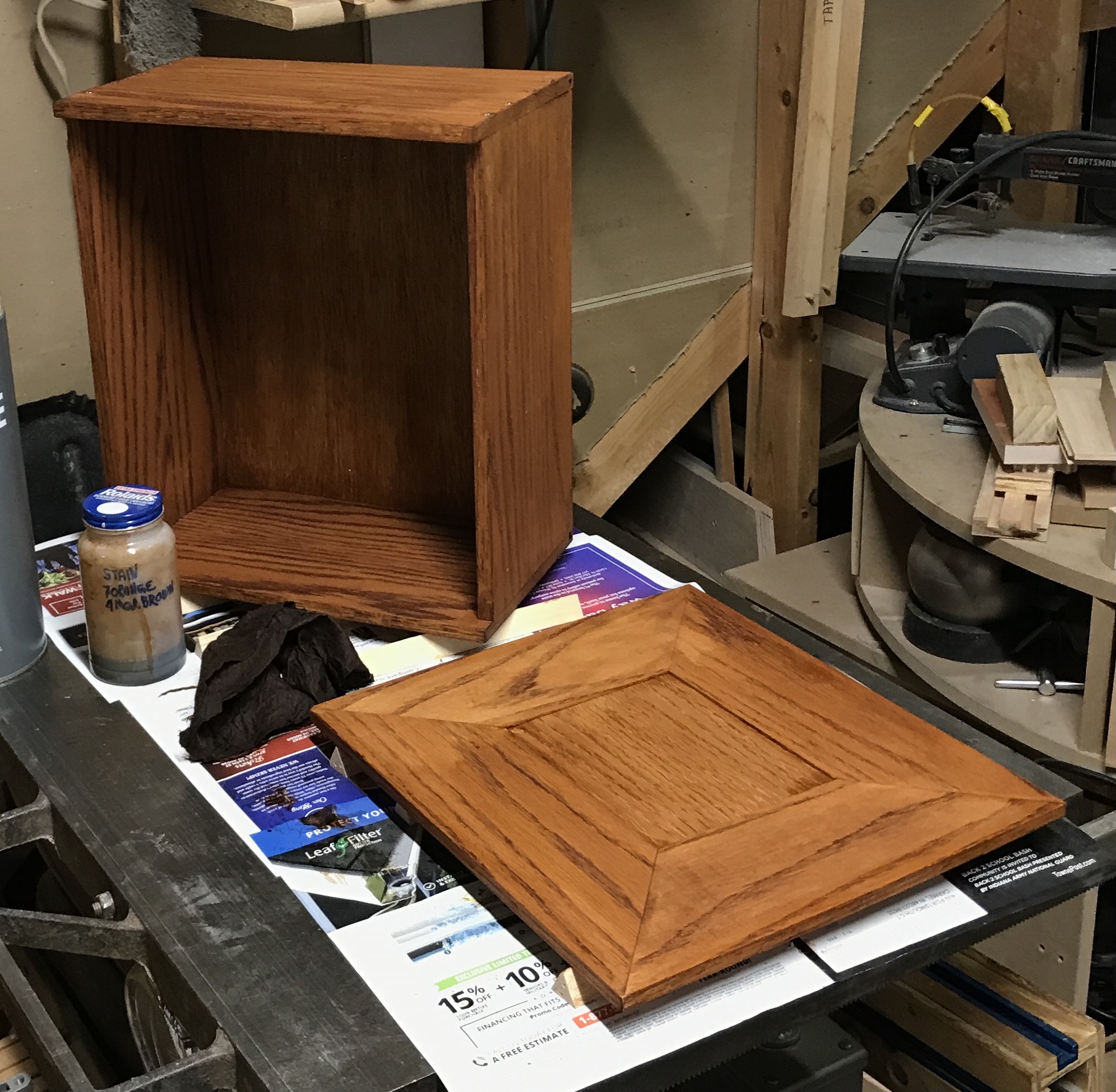
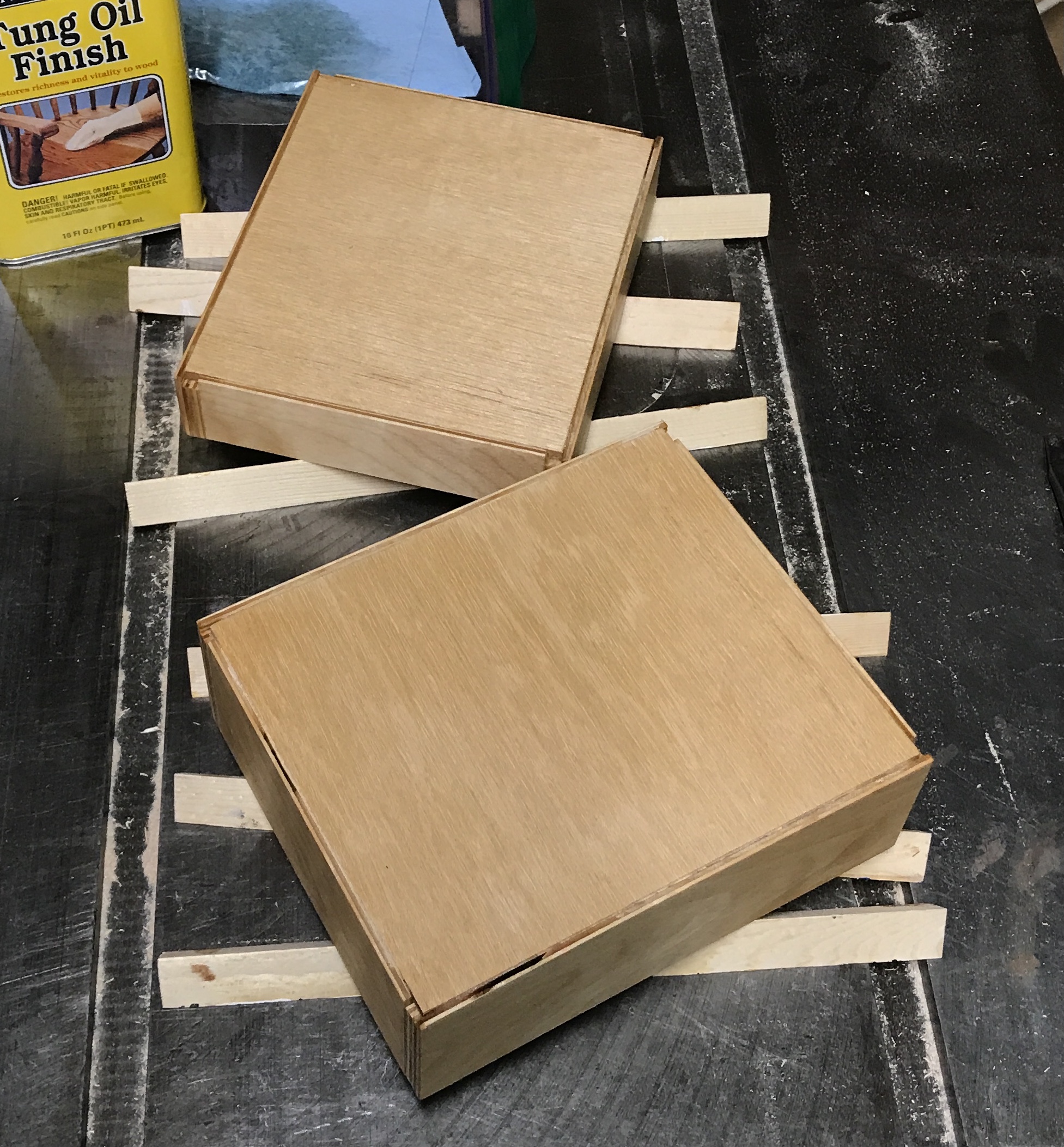
Before finishing the outside of the case needs more sanding. The case was sanded all over again with 220 grit using the oscillating sander. The dust was removed. The case was stained with the General Finishes 7 parts orange to 4 parts med brown combo used on the Greene and Greene side table. The stained box and door are seen below.
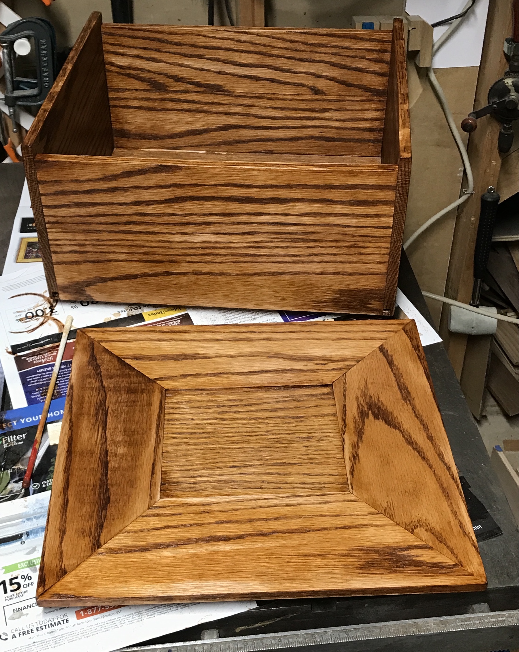
The water based stain really raised the grain. More sanding was needed than expected. This left the stain washed out in places, a more antique look than planned. The stain will be left to dry overnight before applying shellac.
Three coats of shellac were wiped on this morning. The parts were sanded before the first coat and after each coat. The coats were left to dry for one hour before applying the next. As usual I am not thrilled with the finish, but it is sufficient for this rather workmanlike box.
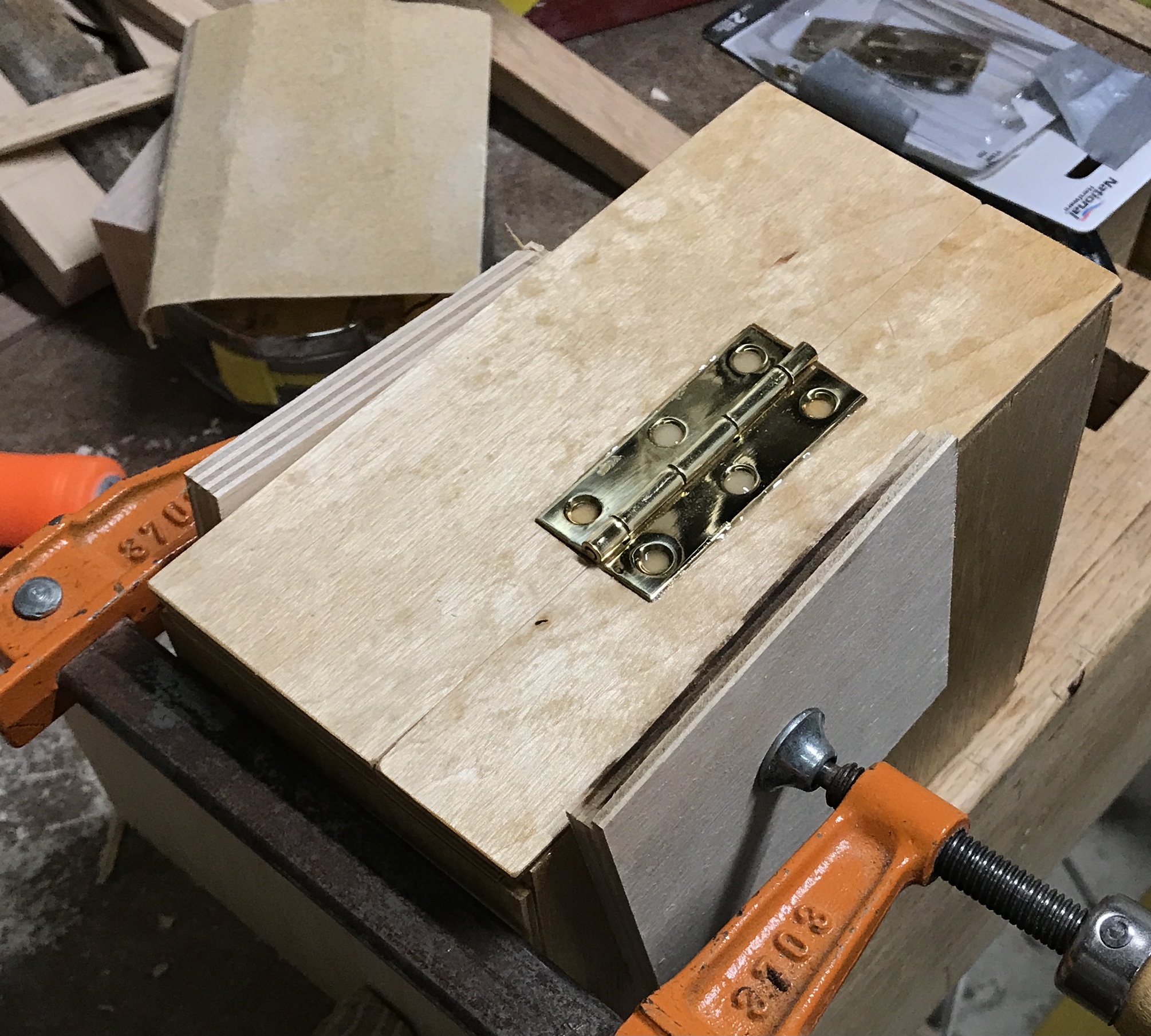
Hanging the door was next. To this end the hinge locations were laid out. Three hinges were used. The hinge on center was marked out with my marking knives. The center of the box was supported with some scrap wood. The marked rectangle was mortised with a chisel to the depth of the hinge. The other two hinges were aligned 2" from the outside of the box. They were mortised similarly. The photo shows the mortises with one hinge in place.
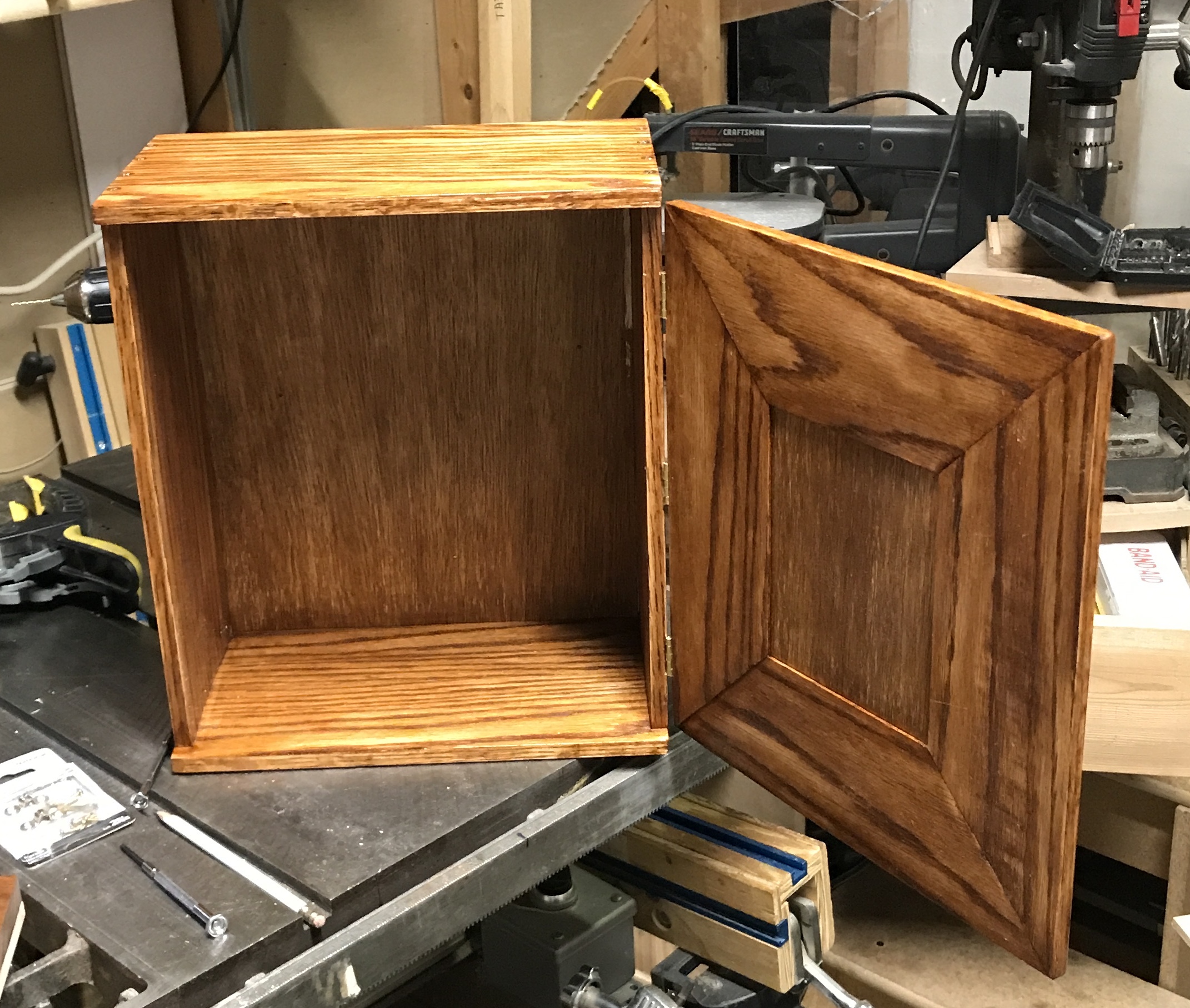
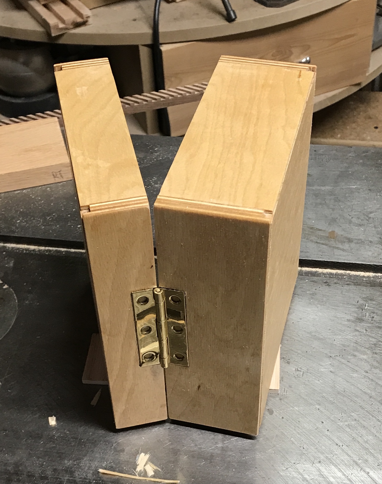
The three hinges were installed after marking the hole locations and drilling them with a 1/16" drill. The door was aligned with the box body and held in place. The center hinge was marked with the marking knives. A chisel was used to make the mortise. The other two hinges were marked out and their mortises chiseled out. These mortises extended across the entire 1/2" width of the door. The hole locations were marked and drilled. The three hinges were attached to the door. The first photo shows the three installed hinges. The second shows the open box. The door fit is perfect.
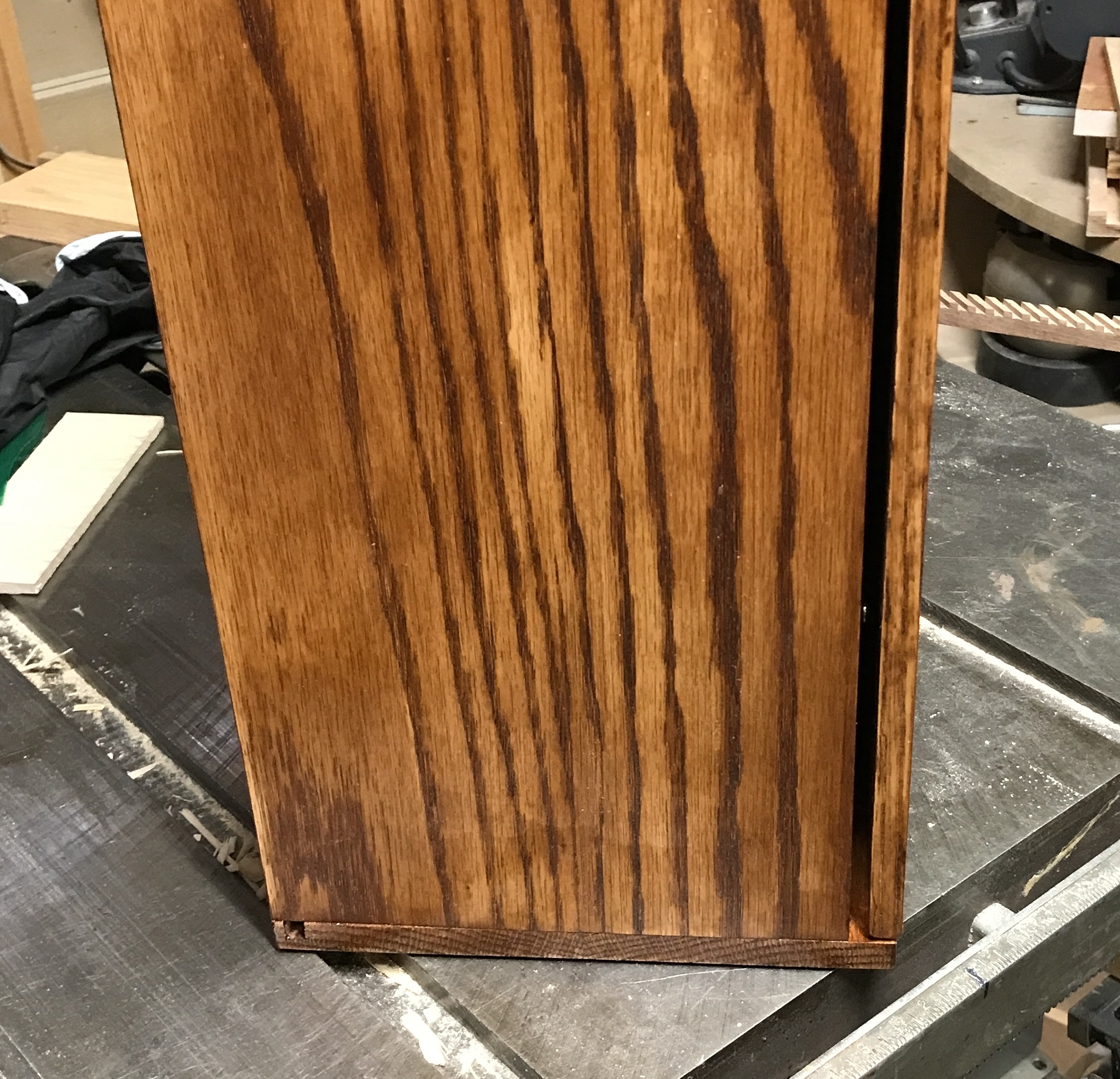
The red oak was not a great choice for making this box. The grain is too open. It is almost impossible to sand smooth as some of the grain is much softer than others. The resulting finish is rough. The grain also takes up stain very non-uniformly. The box looks like zebra hide.
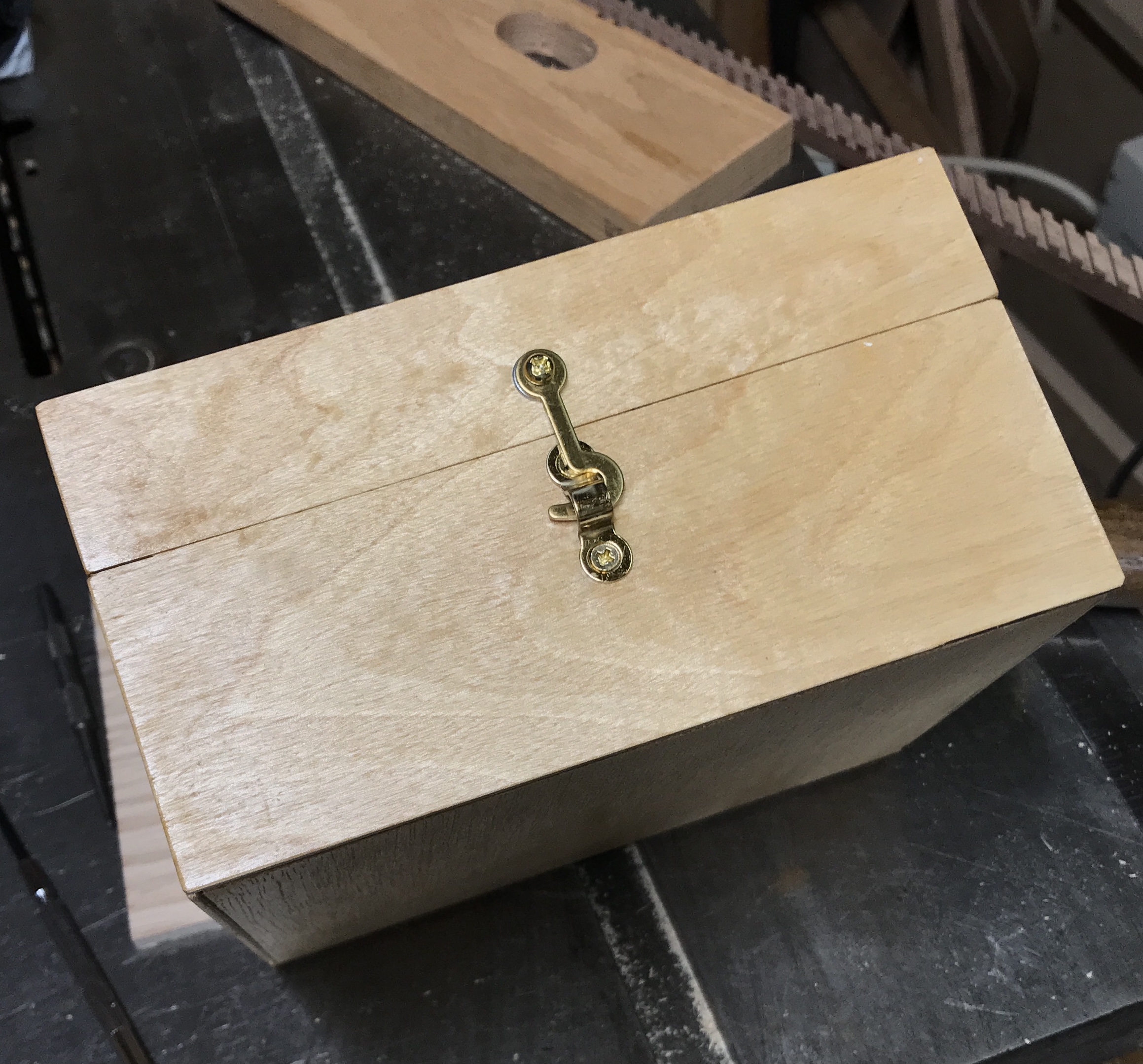
Various options were considered for latching the box closed. The option settled on is using a pin inserted in a hole in the top of the box that extends into the door. This is simple and effective. A chain is needed to attach the pin to the box.
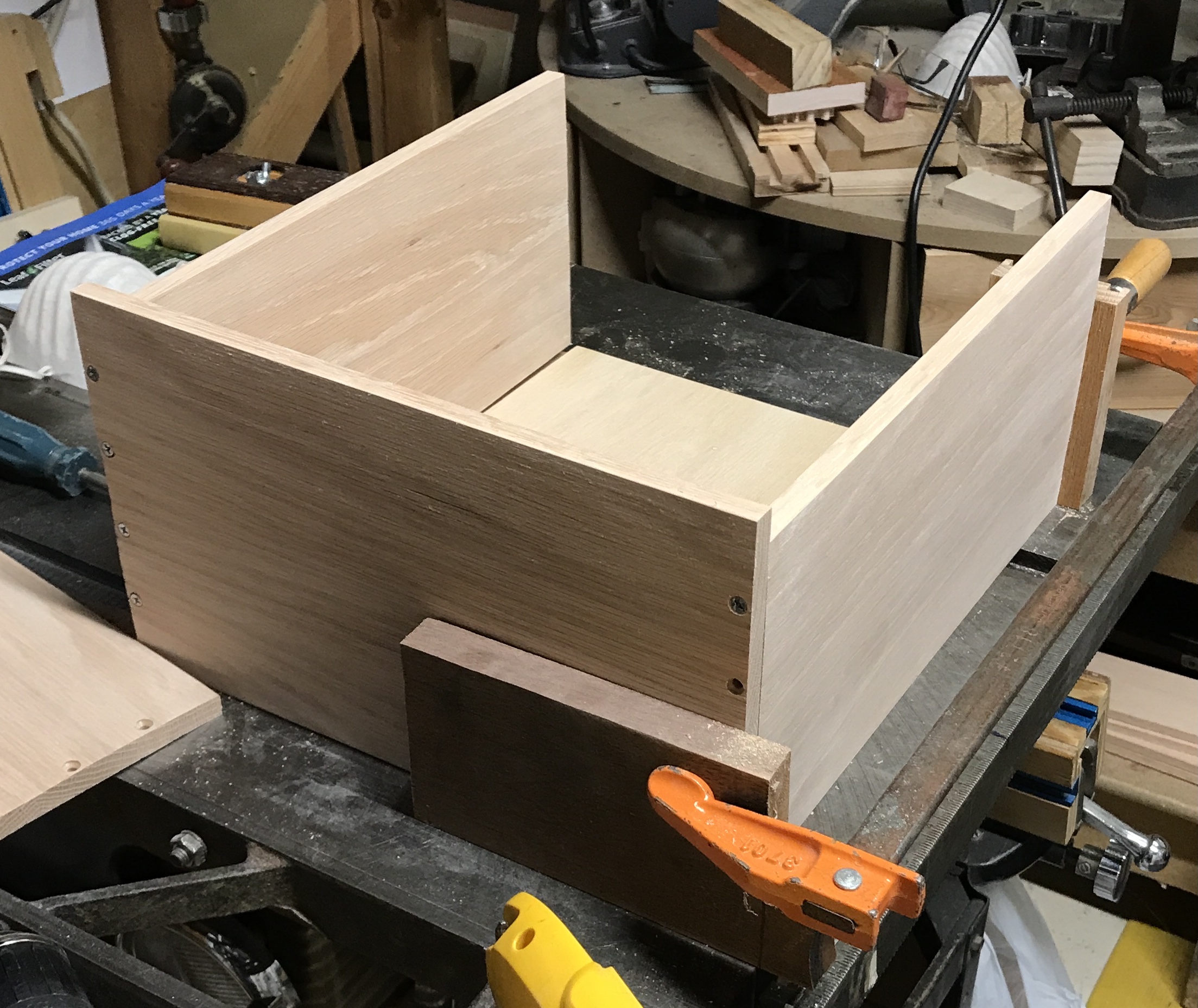
While considering the closure and the handle the boxes inside need to be made. The first box, the largest, will hold the light fixture. This box will fit in the upper left corner of the case. There is plenty of room so the box was made 4" X 6" X 7". A scrap of 3/8" plywood was found. It was cut into four sides: two 4 X 7" and two 4" X 5 3/4". The joinery is simple butt joints for the sides. The top and bottom are to be inset into these sides. Two 5 3/4" X 6 3/4" rectangles were cut from 3/16" plywood.
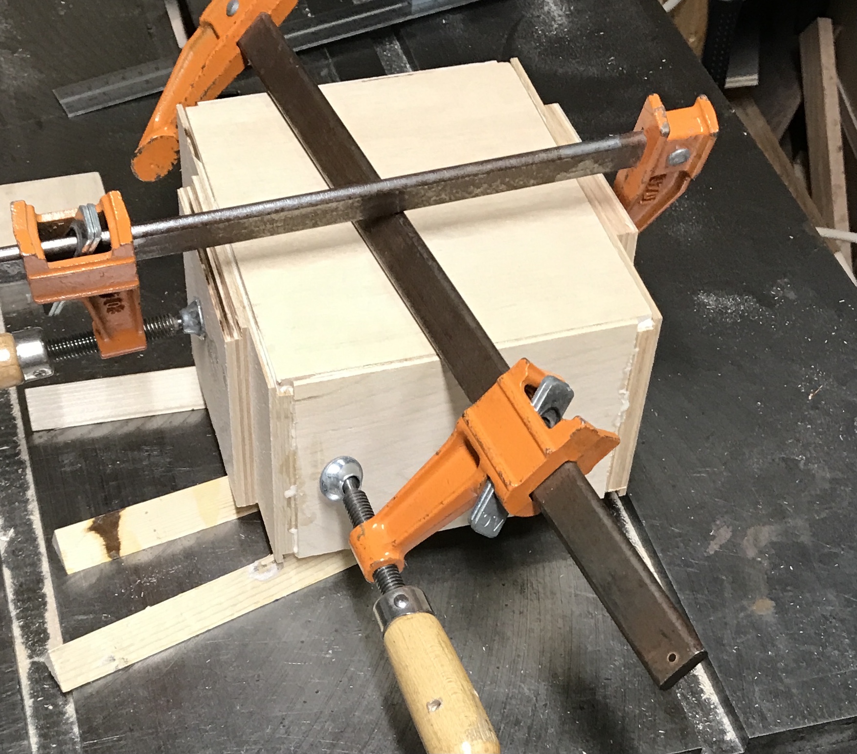
Rabbets were cut for on the long edges of all four sides. The saw blade was set at 1/4" and the blade was set 3/16" from the fence. The pieces were all assembled. The top and bottom needed to be recut a bit less than the nominal 5 3/4". When the fit was acceptable, glue was applied and the parts were assembled. The photo shows the glue-up. (The loose clamp is serving as weight for the box top.)
The table saw fence was adjusted until about one third of the box was beyond the blade. The box was cut on all four sides and separated into a top and a bottom as seen in the first photo below. All sides of the box were sanded to 220 grit. The dust was removed. The first coat of tung oil was applied with a shop cloth. The box at this stage is seen in the second photo.
Two more coats of tung oil were applied; sanding between coats. After drying a hinge was located. It is really too big for this box. Since no screws will fit the hinge and not go through the 3/8" box wall, glue was chosen to affix the hinge. The hinge was centered on the edge of the bottom box. It was outlined with marking knives. The area marked was chiseled out down to the second layer of plywood. The boxes were clamped together. The hinge location was marked on the box top. This was chiseled out. The opening was not large enough to fit the hinge with the top tight to the bottom. The opening on the bottom was opened up a bit. The hinge fit well, so it was glued in place with two part epoxy. The first picture shows the hinge set in the glue. I was sufficiently careful applying the glue that the box opens and the hinge flexes.
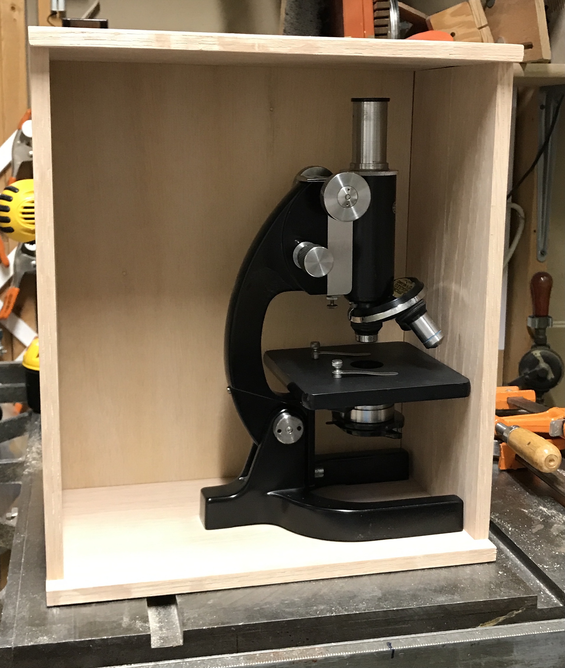
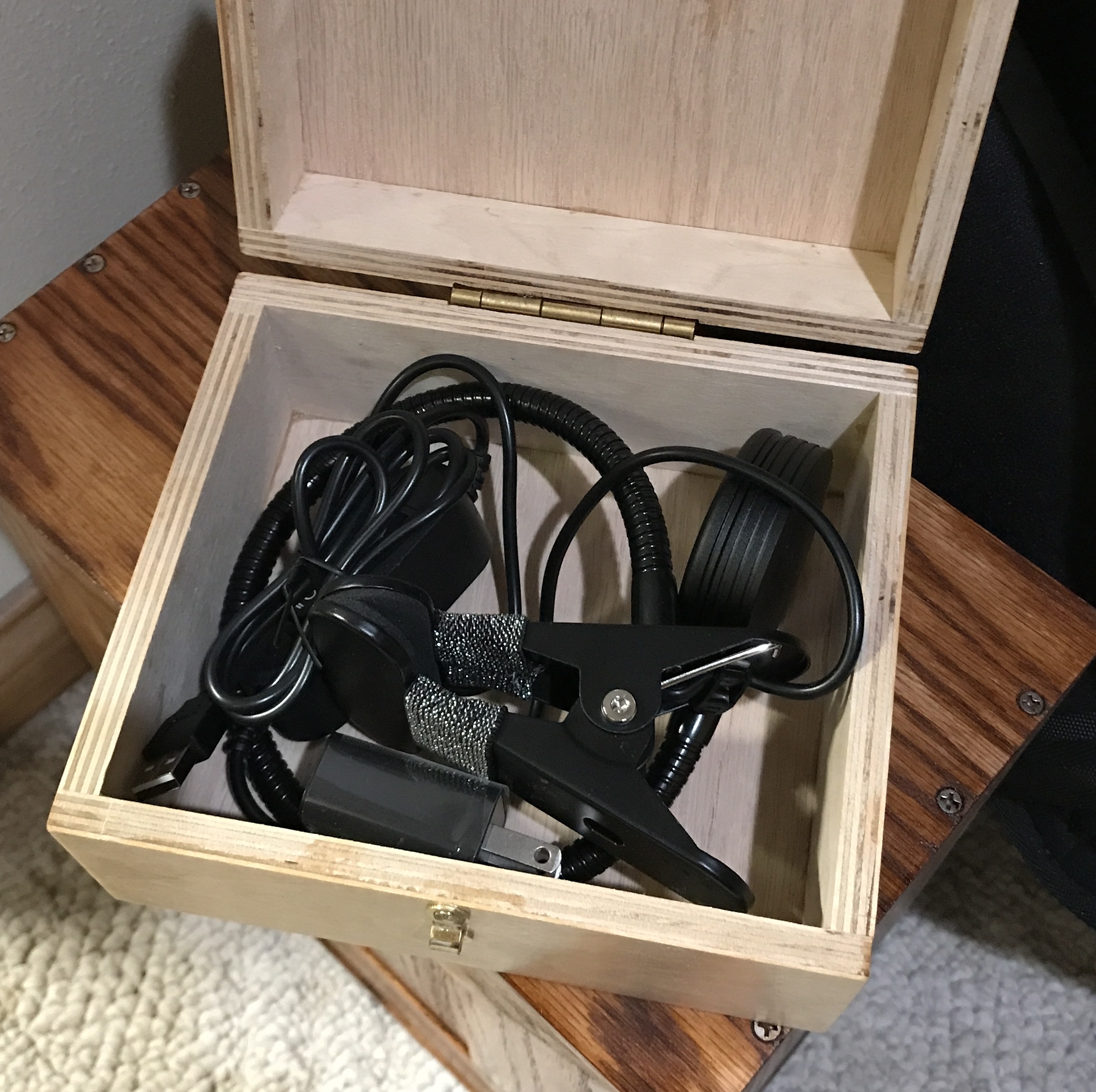
The opposite side of the box was marked for the hook "eye". The box was drilled 3/32" and the holes chamfered. Two screws with their point filed off held the eye. The hook was aligned above the eye and marked. A hole was drilled. A #6 washer was used to raise the hook enough to clear the ends of the eye. The hook was screwed into place as seen below. The light and its trappings easily fit in the box.
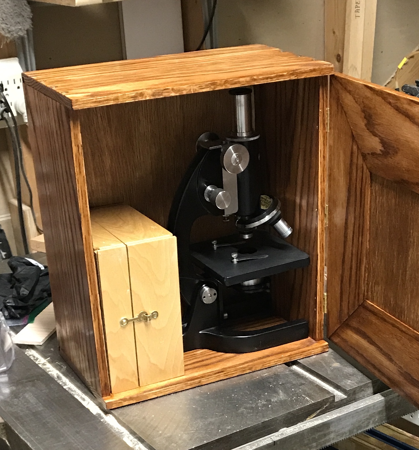
Slight error in calculations. The size of the box did not account for the two newly installed protrusions. The light box fits nicely in the corner next to the microscope as planned. However, the door no longer shuts all the way. There is a 1/4" gap when the door hits the latch.
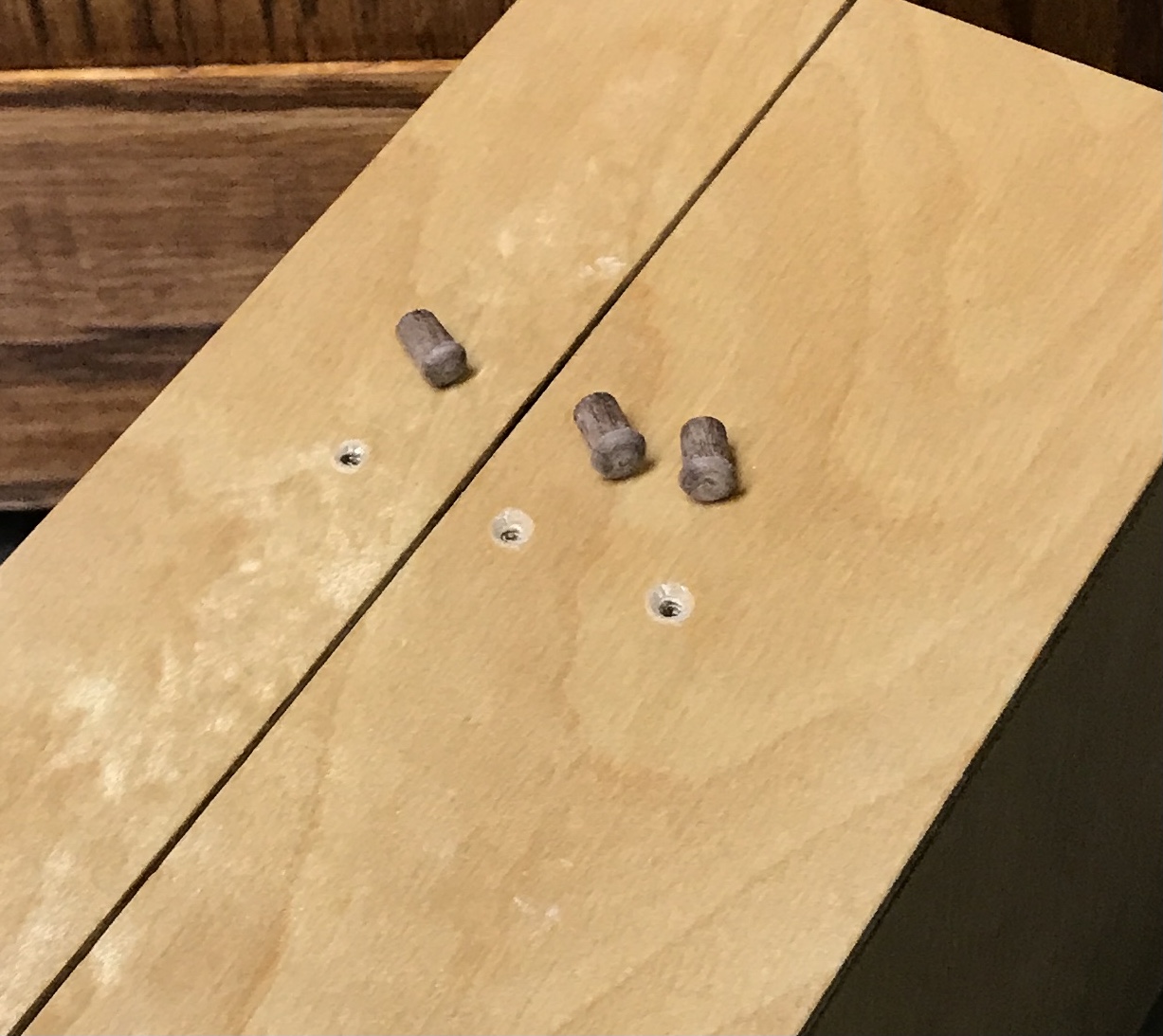
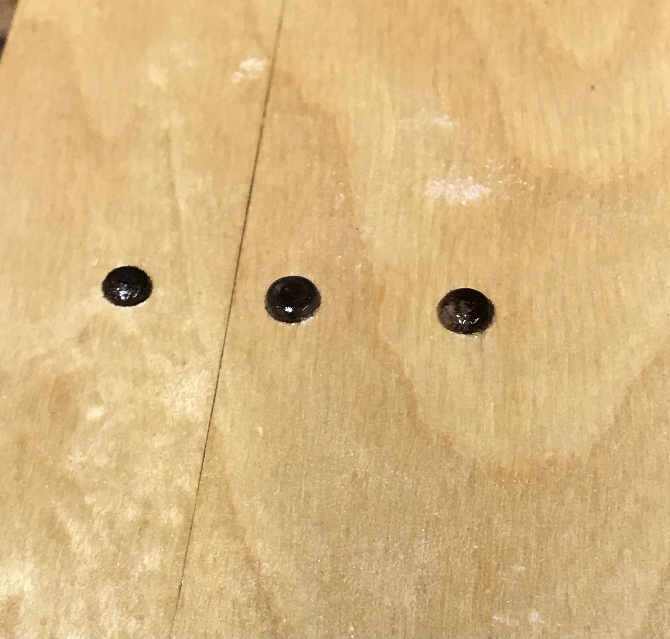
The hinge is also protruding. There is enough leeway in the fit to accomodate the hinge, but not both it and the latch. The latch will be moved to the side, seen on top in the picture above. The latch was moved. Three plugs were made for the holes. A short length of 3/8" X 1/4" walnut was held in the four jaw chuck. 5/16" was reduced to 1/4" and 1/4" was further reduced to 3/16". The little plug was parted off at 5/16". The part was held by the 3/16" end in a collet and the head was rounded with a file and sanded. Two more were made similarly. The holes were opened with a 0.180" drill and then reamed to 0.188". The plugs were glued into the holes and a drop of shellac was put on the heads.
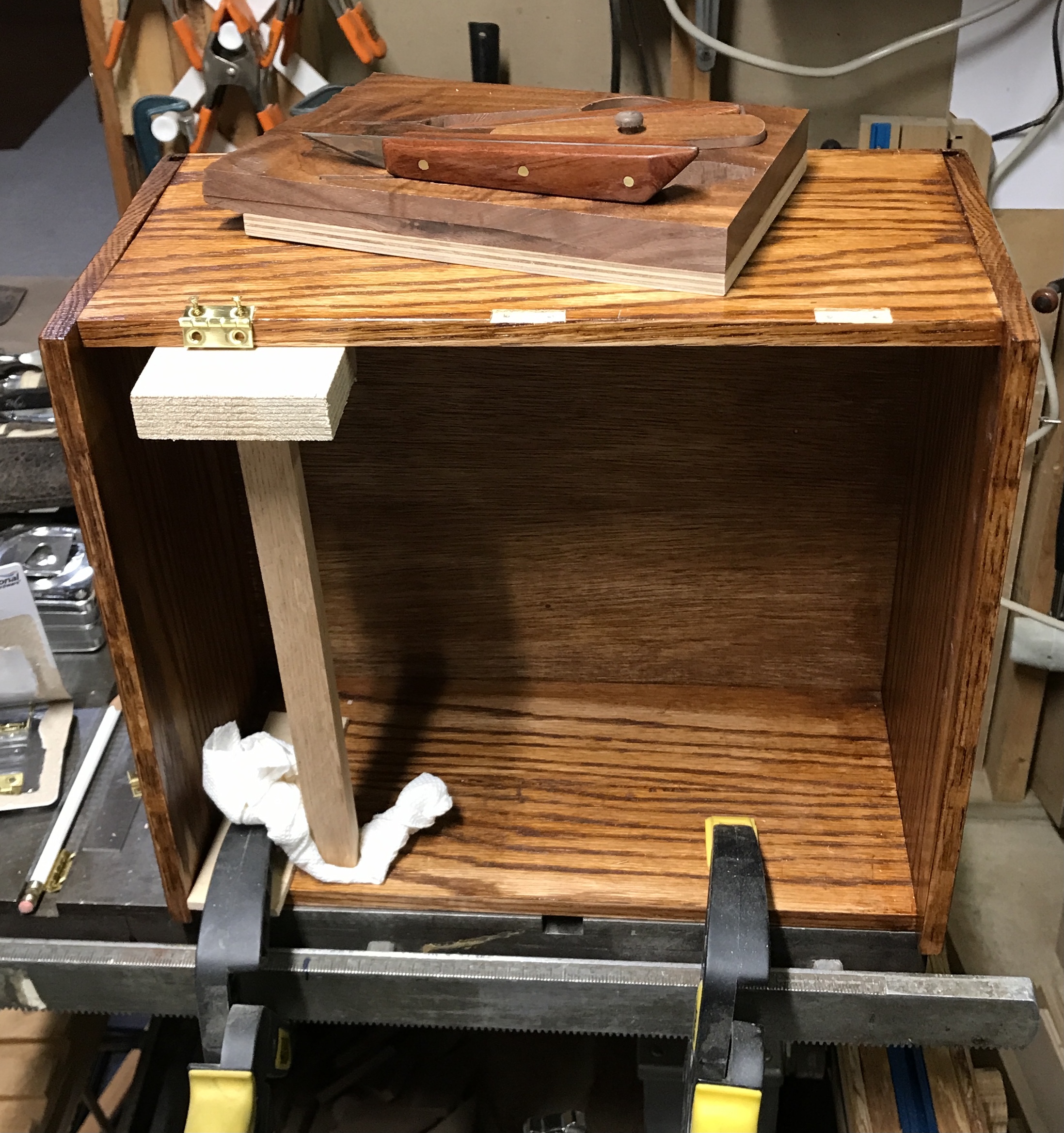
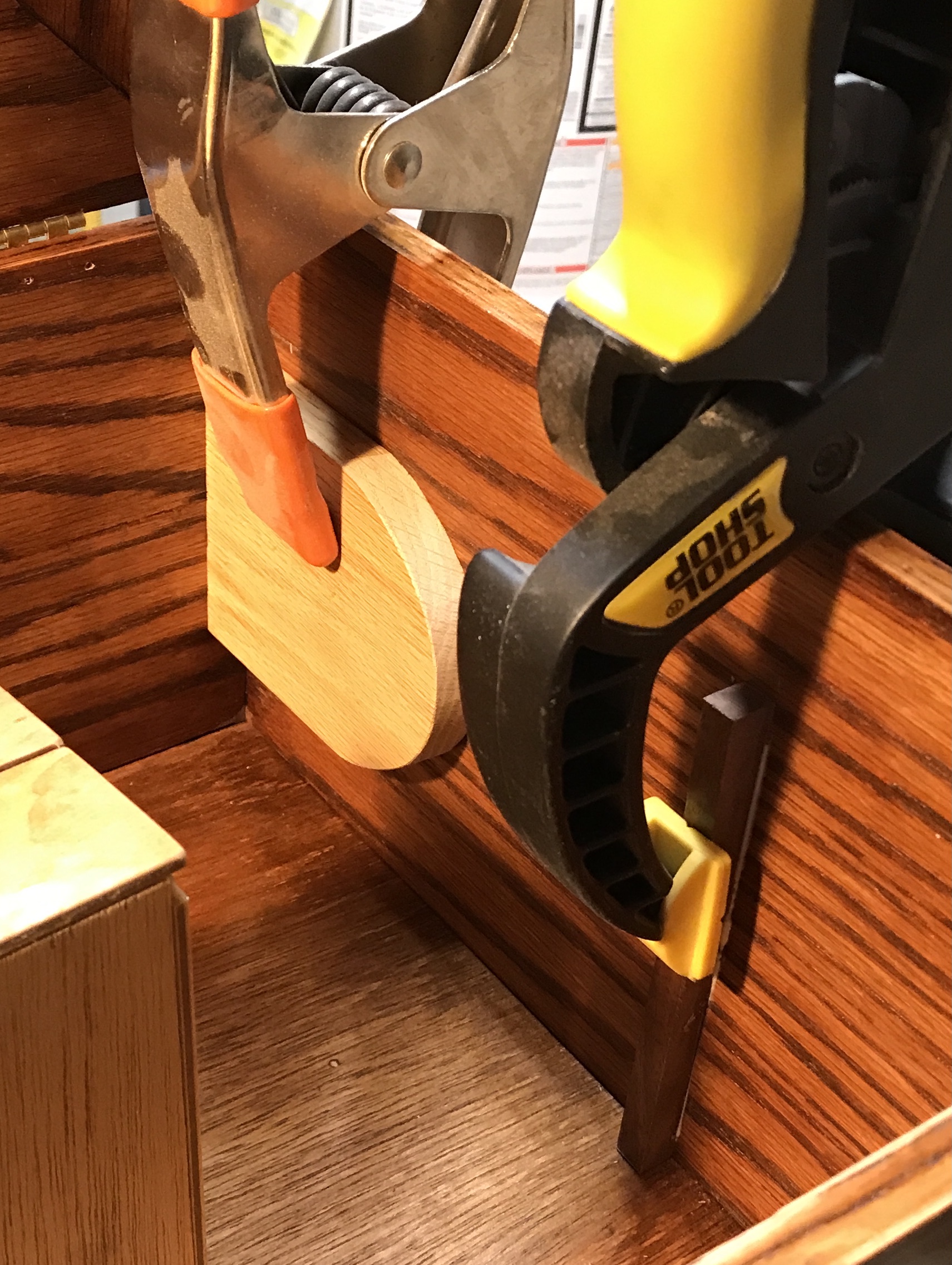
Two stops were made for the inside of the case. The first is for the base of the microscope, a rectangle with one end round. The second is just a strip along the bottom of the case to hold the light box in place. The microscope stop was made from a scrap of 1/2" oak. It was cut to 4 1/8". The bottom of the pencil holder was used to sketch a semi-circle on one end. This was cut with the scroll saw. A little sanding and this part was completed. No finish will be applied. It was glued into place. The same 3/8" X 1/4" scrap from above was used for the second stop. It was cut to length and the ends were sanded. It was laid against the side of the box, marked, and glued in place. The photo below shows the two clamped parts.
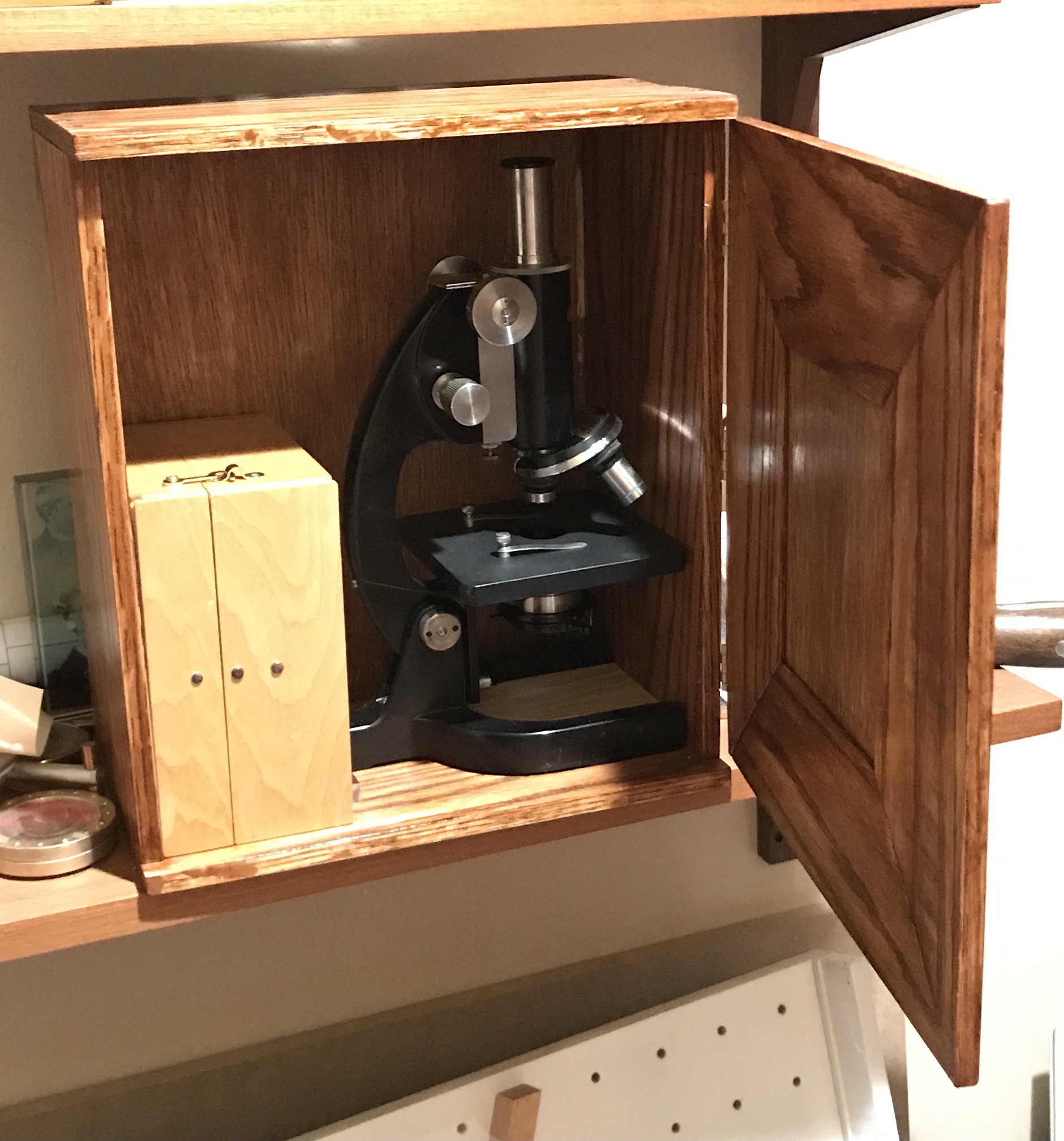
Below is a photo of the case at this point after adding hinges.
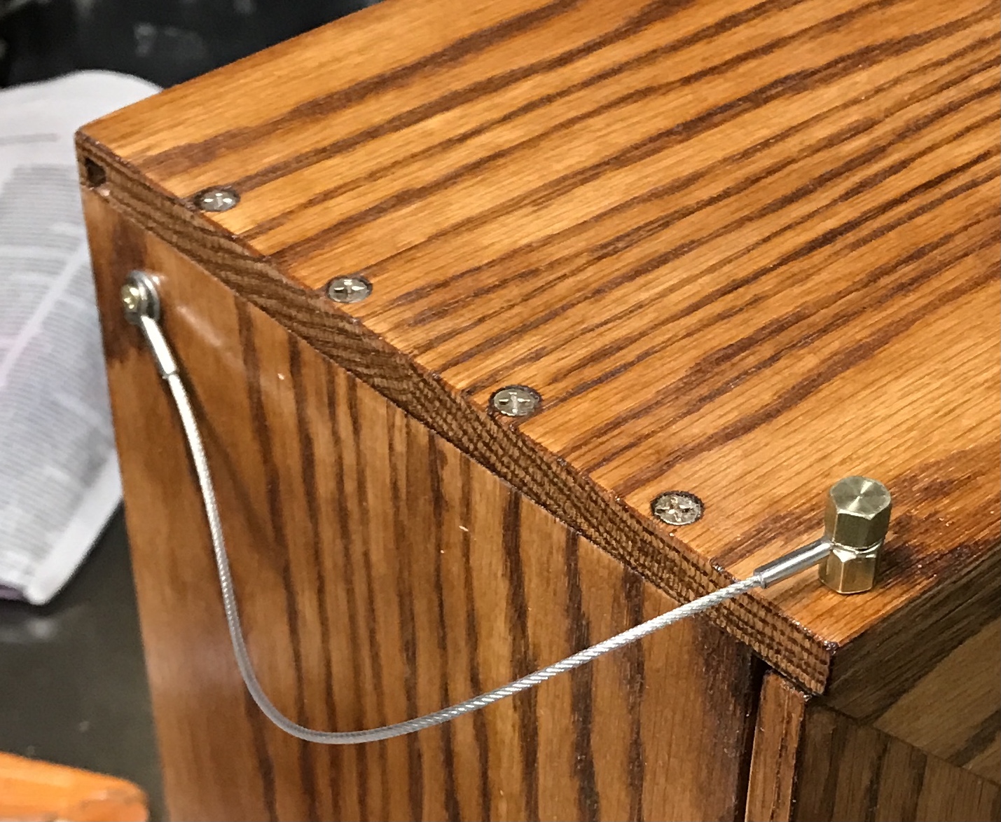
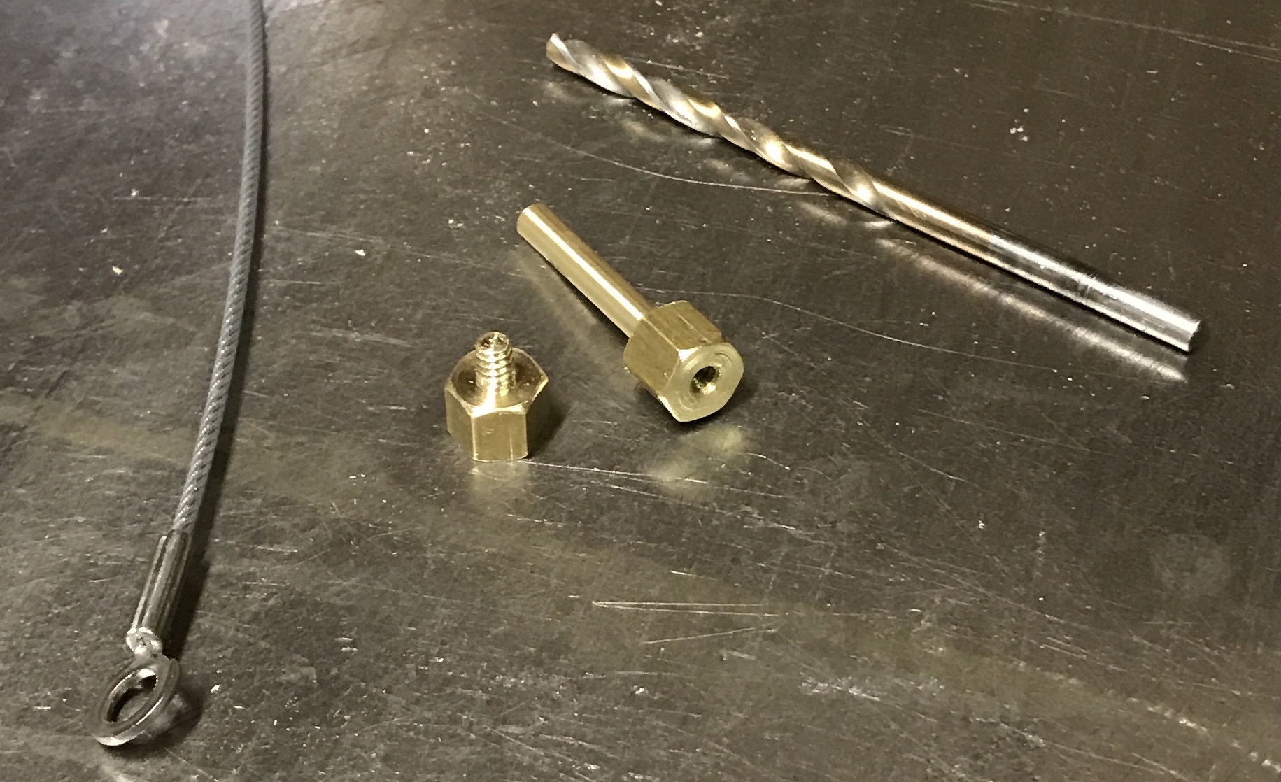
I struggled to find a chain to hold a pin, but seven months later found a cable used for keeping cabinet doors from opening too far. The cable has eyelets on either end. A screw will affix one end to the box. A special pin needs to be made to fit the other end, essentially a pin with a screw hole in one end.
The pin was made without a plan. A 1 1/2" length of 3/8" brass hex was found in the scrap box. A 1/4" of one end was reduced to 0.137" and threaded with a 6-32 die. The screw was parted off 1/2" from the end. The ends were lightly chamfered. The remaining length was center drilled and supported with a tailstock center. It was reduced to 0.140" in diameter for 3/4". The part was flipped and held by the reduced section. The opposite end was center drilled, drilled with a #29 drill and tapped 6-32. The screw had to be shortened a bit before the gap between it and the nut was about right for the eyelet. The photo below shows the parts at this stage.
The case was marked and punched for drilling. The door was held shut with a clamp. The case and door were drilled with a 1/8" drill followed by a #26 drill and eventually by a #27 drill for and easy fit. The side of the case was drilled and a small brass screw was installed with a washer and one end of the cable. The photo below shows the parts in place on the case. The screw and the nut were sanded to 2000 grit for a nice finish. They were also painted with varnish.